

Hydraulic System Troubleshooting Guide for 2026
Our hydraulic system troubleshooting guide walks fleet teams through pump, valve, and pressure diagnostics to cut downtime and avoid costly guesswork.
Loading article…
Article Not Found
The article you're looking for doesn't exist or may have been removed.
Back to BlogKey Takeaways
- Start with fluid level and quality. Low or contaminated oil causes most common hydraulic failures.
- Classify the problem as pressure or volume before changing any parts.
- Test the pump and relief valve together to isolate pressure loss and flow issues.
- Check the pump suction strainer for cavitation. A clogged strainer is a frequent root cause of pump noise and pressure loss.
- Document every component change. One wrong part number can defeat an entire repair.
A hydraulic system troubleshooting guide is a structured process that starts with fluid inspection, moves through pressure and flow testing, and ends with component-level diagnosis. We built this guide to help you isolate pump, valve, cylinder, and heat problems before they cause downtime.
How a Hydraulic System Troubleshooting Guide Prevents Component Failure
A hydraulic system troubleshooting guide prevents component failure by replacing guesswork with a sequence of tests that narrow down the actual cause before any part gets replaced. Without this kind of structure, maintenance teams often fall into parts-swapping, which increases downtime and cost without identifying the true failure mode. We've organized this diagnostic sequence so each step eliminates a category of possible causes.
Common Root Causes of Hydraulic Failure
According to Cross Manufacturing, gradual or sudden loss of pressure or flow resulting in a loss of power is common in hydraulic system failure. Any one of the system's components may be at fault: the pump, relief valve, directional valve, cylinder, or even the fluid itself. The most frequently encountered issues include contaminated fluid, clogged suction strainers, air leaks on the inlet side, worn pump internals, and misadjusted relief valves.
"What happens in many plants is that troubleshooting is done by a parts-changing process, which can be expensive in downtime and part costs. When the machine finally becomes operational, no one has learned anything because so many random things were done." - Al Smiley, GPM Hydraulic Consulting, via Machinery Lubrication
Why Pressure and Flow Are the First Diagnostic Categories
Most hydraulic issues fall into one of two categories: pressure or volume. A pressure issue is a condition where the system cannot build enough force to perform the required work. A volume issue is a condition where the pump isn't delivering the required amount of oil, or fluid is bypassing somewhere in the system. According to Machinery Lubrication, a press may require 3,000 psi to machine a part but only build to 2,000 psi, that's a pressure problem. If the issue is speed-related instead, a volume problem is likely occurring.
Tools and Documentation You Need Before Starting
Before opening the system, gather a pressure gauge, a hydraulic schematic, the latest oil analysis report, and any maintenance records. The Surplus Center's Fluid Power Data Book, available at Surplus Center, is a condensed collection of fluid power data and references that includes troubleshooting procedures. Also record recent changes: has any component been replaced? Were pressure or electrical adjustments made? These facts often shorten the diagnostic path considerably.
Step 1: Inspect Hydraulic Fluid and Suction Strainer
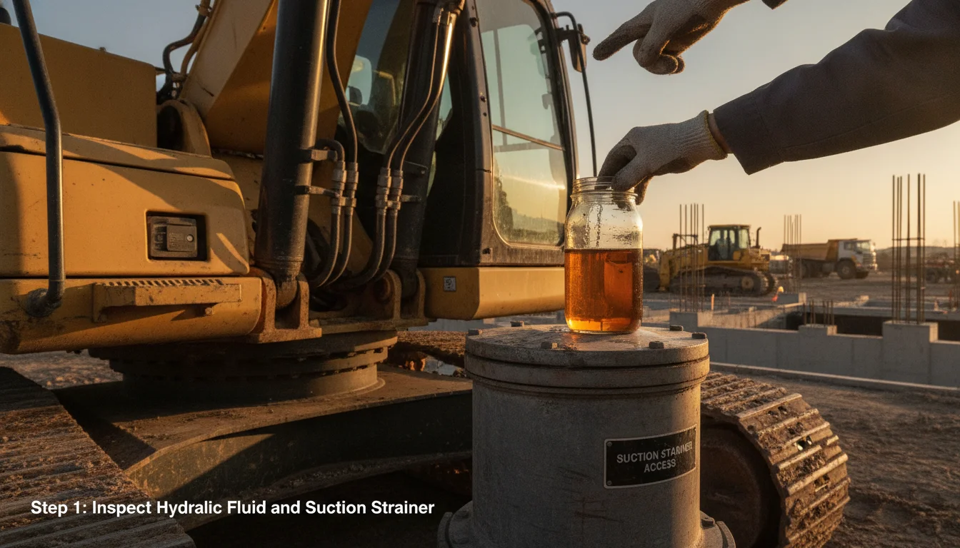
Inspecting fluid and the suction strainer is the correct first move in any hydraulic system troubleshooting guide because fluid condition and inlet restriction cause more failures than any other single factor. The system should be at normal operating temperature, about 100 degrees Fahrenheit, before you start testing. Skipping this step wastes hours chasing symptoms that a clean fluid check would have solved.
Check Fluid Level and Quality
Hydraulic fluid level must be within the manufacturer's recommended range. Low fluid levels can cause cavitation, allowing air to be drawn into the pump. Examine the fluid itself: it should be clean, clear, and free from contaminants. Dark, milky, or foamy oil indicates oxidation, air entrapment, or water contamination. If the level is low, top it up first, but don't ignore the reason it became low.
Clean or Replace the Pump Suction Strainer
A suction strainer is a coarse filter element installed at the pump inlet to stop debris from entering the pump. A clogged suction strainer generally produces increased pump noise, loss of pressure, loss of speed, and loss of flow. Remove the suction strainer and inspect it for blockages. Clean or replace it if necessary, and make sure no contaminants get reintroduced when reinstalling.
Look for External Leaks and Inlet Restrictions
Visually inspect the pump, hoses, and fittings for any signs of leakage. External leaks may point to damaged seals, cracked hoses, or loose connections. On the suction side, a small air leak can cause erratic operation even when no oil is visible. Tighten or replace suspect fittings and check the inlet line for collapsed hoses or restrictions.
Step 2: Test Pump Pressure and Relief Valve Performance

Testing pump pressure and relief valve performance together isolates which of the two components is actually failing. Once fluid and inlet checks are complete, test the pump to confirm it's delivering fluid as expected. The pump and relief valve work as a pair, so a pressure test at this stage saves you from replacing the wrong part.
Monitor System Pressure with a Gauge
Install a reliable pressure gauge and compare the reading to the manufacturer's recommended range. Low pressure output may indicate internal pump wear, incorrect relief valve settings, or restricted flow. A reading that's too high may indicate a blockage or a malfunctioning relief valve. According to Hyspeco, abnormal pressure levels signify various underlying issues and should be checked regularly.
Diagnose Pump Cavitation, Overheating, and Noise
Cavitation is the formation of vapor cavities in the hydraulic fluid when pump inlet pressure drops below the fluid's vapor pressure. Loud whining or knocking noises are often the result of cavitation or air being drawn into the system due to a clogged suction strainer or low fluid levels. Overheating often results from internal friction caused by fluid contamination, misalignment, or insufficient lubrication.
Four Common Pump Problems and Solutions
- Pump is not delivering pressure: worn pump components, clogged suction strainer, or incorrect pressure settings. Clean or replace the strainer, inspect internals, and verify relief valve settings.
- Pump cavitation: low fluid levels, blocked suction strainer, or restricted inlet lines. Correct fluid level, clean the strainer, and inspect the inlet line for restrictions.
- Pump overheating: contaminated fluid, insufficient cooling, or over-pressurization. Change or filter the hydraulic fluid, inspect cooling mechanisms, and verify pressures are within pump specifications.
- Noisy pump operation: air in the system or worn internal parts. Check for loose fittings or damaged seals that may introduce air, and replace worn components.
Step 3: Isolate Pressure, Flow, and Directional Control Problems
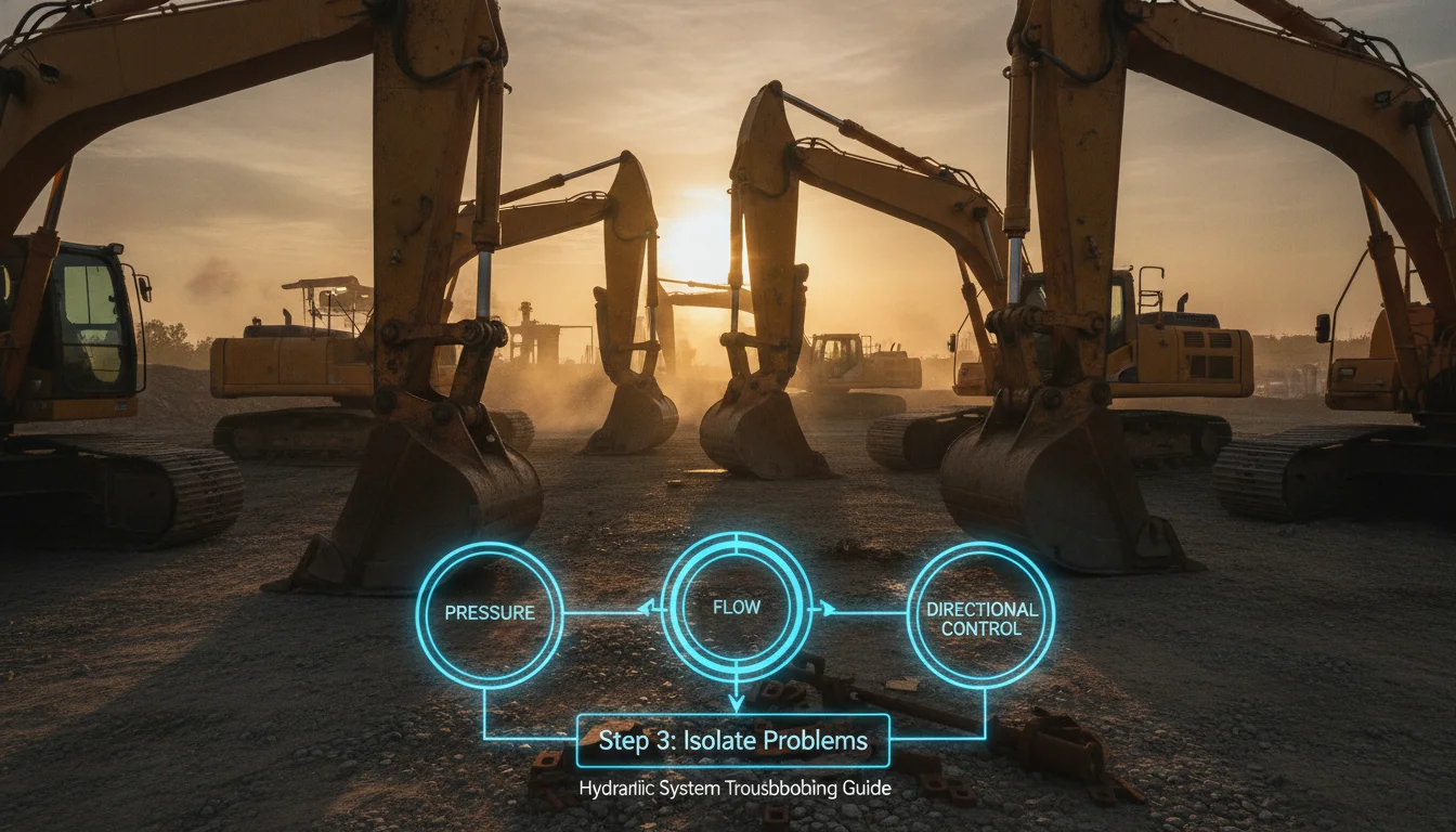
Isolating pressure and flow problems means sorting the failure into one of four conditions: no pressure, low pressure, erratic pressure, or excessive pressure, each of which points to a different set of causes. This part of our hydraulic system troubleshooting guide separates those conditions so you can follow the correct branch instead of guessing.
No Pressure vs. Low Pressure
According to Airline Hydraulics, the condition of no pressure is most often caused by no flow from the pump. Low pressure can be caused by a pressure relief path that exists, a pressure-reducing valve set too low, a damaged pump, motor, or cylinder, or a worn relief valve. Verify the pump is actually producing flow before you touch any valve adjustment.
Erratic Pressure and Air Entrainment
Erratic pressure is typically caused by air in the fluid, a worn relief valve, contamination in the fluid, a defective accumulator, or a worn pump, motor, or cylinder. Air in fluid requires tightening leaking connections, filling the reservoir to the proper level, and bleeding air from the system. Replace dirty filters and system fluid when contamination is present.
Excessive Pressure and Relief Valve Settings
Excessive pressure usually points to a pressure-reducing, relief, or unloading valve that is misadjusted. A relief valve is a pressure-limiting device that opens to protect the system when pressure exceeds a set threshold. On variable displacement pumps, an inoperative yoke actuating device can also cause excessive pressure. Install a pressure gauge and adjust to the correct valve setting pressure.
Step 4: Evaluate System Heat and Oil Condition
Evaluating heat means treating it as both a symptom and a cause of hydraulic failure rather than an afterthought. Excessive heat degrades oil, damages seals, and accelerates wear across the entire circuit. Any complete hydraulic system troubleshooting guide has to give heat its own diagnostic category.
Causes of Overheating Oil
Oil can overheat when it passes through a relief valve for excessive time, so return the control valve to neutral when it's not in use. Other causes include incorrect oil, low oil, dirty oil, an engine running too fast, excessive component internal leakage, restriction in filters or lines, a malfunctioning oil cooler, insufficient heat radiation, and a reservoir that's too small.
Foaming and Contamination
Foaming oil is caused by incorrect, low, or dirty oil, or by air leaks on the suction side. Replace, clean, or add oil as needed, and check the suction line and component seals for suction leaks. Contaminated fluid should be drained and the system flushed before new fluid goes in.
Cooler and Reservoir Sizing
A malfunctioning oil cooler must be cleaned or repaired. Insufficient heat radiation can be addressed by cleaning dirt and mud from the reservoir and components. Cross Manufacturing recommends that reservoir size be 1 1/2 times the pump gpm to provide adequate heat dissipation and deaeration.
Step 5: Inspect Valves, Cylinders, and Load-Holding Components
Inspecting valves and cylinders comes after you've ruled out pump and fluid problems, because these control elements each carry their own distinct failure signatures. Directional valves, pressure control valves, and cylinders don't fail the same way a pump does, so the diagnostic approach shifts here.
Control Valve Centering and External Leaks
A control valve that doesn't center when released can cause load drop. Check linkage for misalignment, spool binding, tie-bolts that are too tight on stack valves, or handle bracket screws that are loose. External valve leaks are often caused by tie-bolts that are too loose, damaged seals, back pressure or restriction in the tank line, or a cracked port or body.
Cylinder Seal Failure and Load Drop
Load dropping with the control valve in neutral indicates leaking cylinder seals or fittings, or a control valve that isn't centering. Replace worn parts. A cylinder that lowers with the valve in the meter-up position may have a damaged or leaky load check, or a leaking cylinder seal. Replace the check or seal as needed.
Troubleshooting Charts for Eight Categories
According to Valmet, troubleshooting charts cover eight categories of hydraulic problems, including abnormal or excessive noise, excessive heat, incorrect flow, and incorrect pressure. Causes are listed in order of probability, with remedies listed adjacent to each cause. This structure helps technicians avoid chasing rare causes first.
Step 6: Use a Systematic Diagnostic Process, Not Parts Swapping
Using a systematic process instead of parts swapping means following a defined sequence of identification, information gathering, and testing rather than replacing components at random. One of the most expensive mistakes in hydraulic maintenance is the parts-changing process. Per Machinery Lubrication, when a machine finally becomes operational after random parts changes, no one has learned anything because so many random things were done.
Identify the Problem as Pressure or Volume
Before touching the system, ask what the machine is actually doing. Is the actuator too weak, or too slow? A pressure issue means the force is insufficient; a volume issue means the speed is insufficient. Intermittent failures are the most difficult to solve, so document exactly when they occur and what the machine was doing at the time.
Gather Machine History and Operator Input
- Identify the problem as pressure-related or volume-related.
- Gather information about any recent pressure or electrical adjustments and component changes.
- Review the hydraulic schematic to understand the circuit path and valve functions.
- Perform system troubleshooting and adjustments with pressure gauges and flow meters.
- Complete a reliability checklist for fluid, filters, alignment, and leaks.
Operator input is critical here. Operators know how the machine feels, sounds, and runs, and they can often identify when a pressure, position, or other indicator is reading incorrectly before a maintenance worker notices anything.
Review the Hydraulic Schematic and Reliability Checklist
A hydraulic schematic is a graphical representation of the system's components and flow paths. Reviewing it before disassembly prevents misdiagnosis. In one case reported by Machinery Lubrication, a positioning problem on an oriented strand-board press in Georgia was traced to a replacement position-control valve with one letter different from the original part number. After 11 hours, the correct valve was installed and the press operated normally. A reliability checklist should include fluid cleanliness, filter condition, leakage, pump coupling condition, and oil analysis results.
"One number or letter difference in the part number may mean that the valve will not work in the system." - Al Smiley, GPM Hydraulic Consulting
Common Hydraulic Failure Modes by Symptom
Grouping failures by symptom means sorting problems into three operating states: inoperative, erratic or slow, and noisy. Use these lists when the initial pressure and flow tests don't point to a single component.
System Inoperative
- No oil in system or insufficient oil, fill system and check for leaks.
- Wrong oil in system, refer to specifications and change oil.
- Filter dirty or clogged, drain oil and replace filter or filter element.
- Oil line restriction, clean or replace dirty or collapsed oil lines.
- Air leaks in pump suction line, repair or replace as necessary.
- Worn or dirty pump, clean, repair, or replace; check alignment and contamination.
- Badly worn components such as valves or cylinders, examine and test for internal or external leakage, then replace faulty components.
- Excessive load, check unit specifications for load limits.
- Slipping or broken pump drive, repair or replace belts, couplings, and check alignment.
System Operates Erratically or Slowly
Air in the system is a frequent cause of erratic operation. Check the suction side for leaks and repair them. Cold oil can slow operation, so allow ample warm-up period. Dirty or damaged components, restrictions in filters or lines, and improper adjustments of orifices or relief valves can also cause slow operation. Tighten fittings and replace seals or damaged lines to correct oil leaks.
Noisy Pump and Blown Shaft Seal
A noisy pump is often caused by low oil level, incorrect oil, or foamy oil. A suction line that is plugged or too small, or an inlet screen that's plugged, also produces noise. Using a pipe fitting in the inlet can restrict flow and should be replaced with the correct fitting. A blown shaft seal on a pump may be caused by wrong pump shaft rotation, while on a motor it may be caused by failure to hook up the drain line.
Hydraulic System Troubleshooting Guide Table: Symptoms, Causes, Remedies
This table consolidates symptom-to-cause relationships from multiple service manuals into one field reference. Use it after completing the initial fluid and pump checks described above.
Comparison Table for Pressure, Flow, Heat, and Noise
| Symptom | Probable Cause | Recommended Action |
|---|---|---|
| No pressure | No flow from pump | Refer to incorrect flow chart; check pump drive and suction line |
| Low pressure | Relief path exists; pressure-reducing valve set too low; damaged pump, motor, or cylinder | Clean, adjust, or replace valves; overhaul or repair components |
| Erratic pressure | Air in fluid; worn relief valve; contamination; defective accumulator; worn pump, motor, or cylinder | Tighten connections and bleed air; replace filters and fluid; repair accumulator |
| Excessive pressure | Pressure-reducing, relief, or unloading valve misadjusted; yoke actuating device inoperative | Adjust or replace valves; overhaul variable displacement pump |
| Excessive heat | Flow losses across relief valve; worn pump; restricted filters or lines; malfunctioning cooler; reservoir too small | Return valve to neutral; clean filters; repair cooler; resize reservoir |
| Noisy pump | Cavitation; air in fluid; coupling misaligned; pump worn | Clean strainer and inlet line; tighten connections; realign coupling; repair pump |
| System inoperative | No oil; dirty filter; air leaks in suction line; worn pump | Fill system; replace filter; repair suction line; clean or repair pump |
How to Use the Table for Fast Isolation
Read the symptom column first, then work through the probable causes in the order listed. Many service charts list causes in order of probability, meaning the first cause is the most likely one. Complete the recommended action for each cause before moving to the next row. This approach prevents unnecessary disassembly and reduces downtime.
Preventive Maintenance and Initial Start-Up Checks
Preventive maintenance turns this hydraulic system troubleshooting guide into a tool you use before failure, not just after it. Many failures can be avoided with a short start-up and maintenance routine. The goal is to catch inlet restrictions, fluid degradation, and alignment problems before they cause a breakdown.
Fluid Cleanliness and Filter Replacement
Hydraulic fluid cleanliness is the foundation of system reliability. Replace filters on schedule, drain contaminated oil, and flush the system before refilling. Advanced Fluid Systems operates as an ISO 9001:2015 certified company and publishes a hydraulic system initial start-up and maintenance guide that outlines basic start-up and maintenance tasks in paragraph and table formats. Use oil analysis reports to verify cleanliness levels before returning the system to service.
Alignment, Belts, Couplings, and Breather Caps
Check pump drive alignment and tension regularly. A slipping or broken pump drive will reduce flow and pressure. Breather caps are often overlooked. In one case described by Machinery Lubrication, an automotive plant changed five pumps in 24 hours after a hose failure. The reservoir had been refilled by removing the breather cap, but a pipe plug was later installed on the threads where the breather was originally mounted. With no place for air to enter the reservoir, the pumps failed repeatedly. Always verify that the breather is installed and clear.
Pro Tip: Before you assume a pump is bad, pull the breather cap and check it's actually open to atmosphere. We've seen entire pump fleets replaced unnecessarily because a maintenance shift accidentally sealed off the reservoir vent.
ISO 9001:2015 and Documentation Standards
Maintenance documentation reduces repeat failures. Record every component change, pressure adjustment, and fluid sample result. A formal procedure aligned with ISO 9001:2015 quality management principles helps ensure consistent troubleshooting and start-up checks across shifts. Keep hydraulic schematics, manuals, and this guide accessible at the machine, not filed away in an office.
Where Genuine and Aftermarket Parts Fit Into Your Diagnostic Plan
Sourcing the right replacement part matters as much as diagnosing the failure correctly. Once your hydraulic system troubleshooting guide points to a worn pump, relief valve, or cylinder seal kit, part quality determines whether the repair holds. We supply OEM-standard hydraulic components for Caterpillar, Komatsu, Volvo, and Atlas Copco machines, and we've seen mismatched or substandard parts undo an otherwise correct diagnosis more than once. If you're troubleshooting a CAT excavator or a Komatsu loader, check our parts categories and brands pages for compatible pumps, valves, and seal kits before you order.
For related maintenance reading, see our guides on hydraulic cylinder seal kit replacement and excavator hydraulic pump maintenance.
Pros and Cons
Pros
- A structured hydraulic system troubleshooting guide cuts diagnostic time by eliminating whole categories of causes early.
- Documentation of part numbers and adjustments prevents repeat failures from mismatched components.
- Following pressure-versus-volume classification avoids unnecessary teardown of pumps or valves that aren't actually at fault.
Cons
- A full diagnostic sequence takes longer upfront than simply swapping a suspected part, which frustrates teams under downtime pressure.
- Requires access to a pressure gauge, schematic, and oil analysis data that not every site keeps on hand.
- Intermittent failures can still take hours or days to trace even with a disciplined process, since the fault may not be present during inspection.
Frequently Asked Questions
What is the most common cause of hydraulic system problems?
Contaminated fluid and a clogged pump suction strainer are among the most common causes. Low fluid levels can also cause cavitation. Always check fluid quality and level first in any hydraulic system troubleshooting guide.
How do I troubleshoot a hydraulic system?
Start by identifying whether the problem is pressure-related or volume-related. Then check fluid level, suction strainer, external leaks, pump pressure, and relief valve settings in that order.
How to reset a hydraulic system?
Stop the machine and relieve stored pressure first. Then check fluid level, inspect for leaks, and verify that control valves center before restarting. Follow manufacturer start-up and safety procedures.
How do you troubleshoot a hydraulic system that is losing pressure?
Check for internal or external leaks, a worn pump, relief valve misadjustment, and a clogged suction strainer. Install a pressure gauge to isolate the failing component.
What causes hydraulic pump cavitation?
Cavitation is caused by low fluid level, restricted inlet lines, or a clogged suction strainer. It produces increased pump noise and loss of pressure or flow.
When should I replace hydraulic fluid?
Replace fluid when it appears dark, milky, or foamy, or when oil analysis shows contamination. Follow manufacturer intervals and replace filters at the same time.
A Hydraulic System Troubleshooting Guide That Works
An effective hydraulic system troubleshooting guide reduces downtime by replacing random parts swapping with a logical diagnostic sequence. It starts with fluid and suction strainer inspection, moves through pressure and flow testing, and then isolates valves, cylinders, and heat sources. The key, as of 2026, remains the same as it's always been: classify the problem as pressure or volume before opening any component.
Summary of Diagnostic Priorities
- Inspect fluid level, quality, and suction strainer first.
- Test pump pressure and relief valve settings together.
- Separate no pressure, low pressure, erratic pressure, and excessive pressure conditions.
- Evaluate heat, foaming, and reservoir sizing as separate failure modes.
- Inspect control valves and cylinders for centering and seal leaks.
Final Reliability Checklist
Before returning any hydraulic system to service, complete a final reliability checklist: fluid clean and full, suction strainer clear, pump pressure within specification, relief valve set correctly, no air leaks on the suction side, filters replaced, couplings aligned, reservoir breather clear, and all adjustments documented. Keep this hydraulic system troubleshooting guide as a standing reference for every hydraulic failure your crew encounters, and when a diagnosis points to a worn pump or valve, shop OEM-quality spare parts with global 5-day delivery at 3genexport.com.